Paxton Net2 Wiring Diagram
Considerations shall be made with regard to the positioning of equipment to. Not all of the equipment shown.
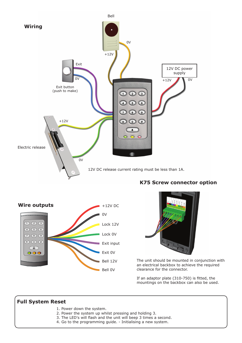
Paxton Net2 Wiring Diagram Wiring Diagram
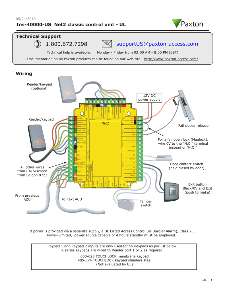
Suitability wiring green white/green 1 screen or spare cores from network cable white/o.
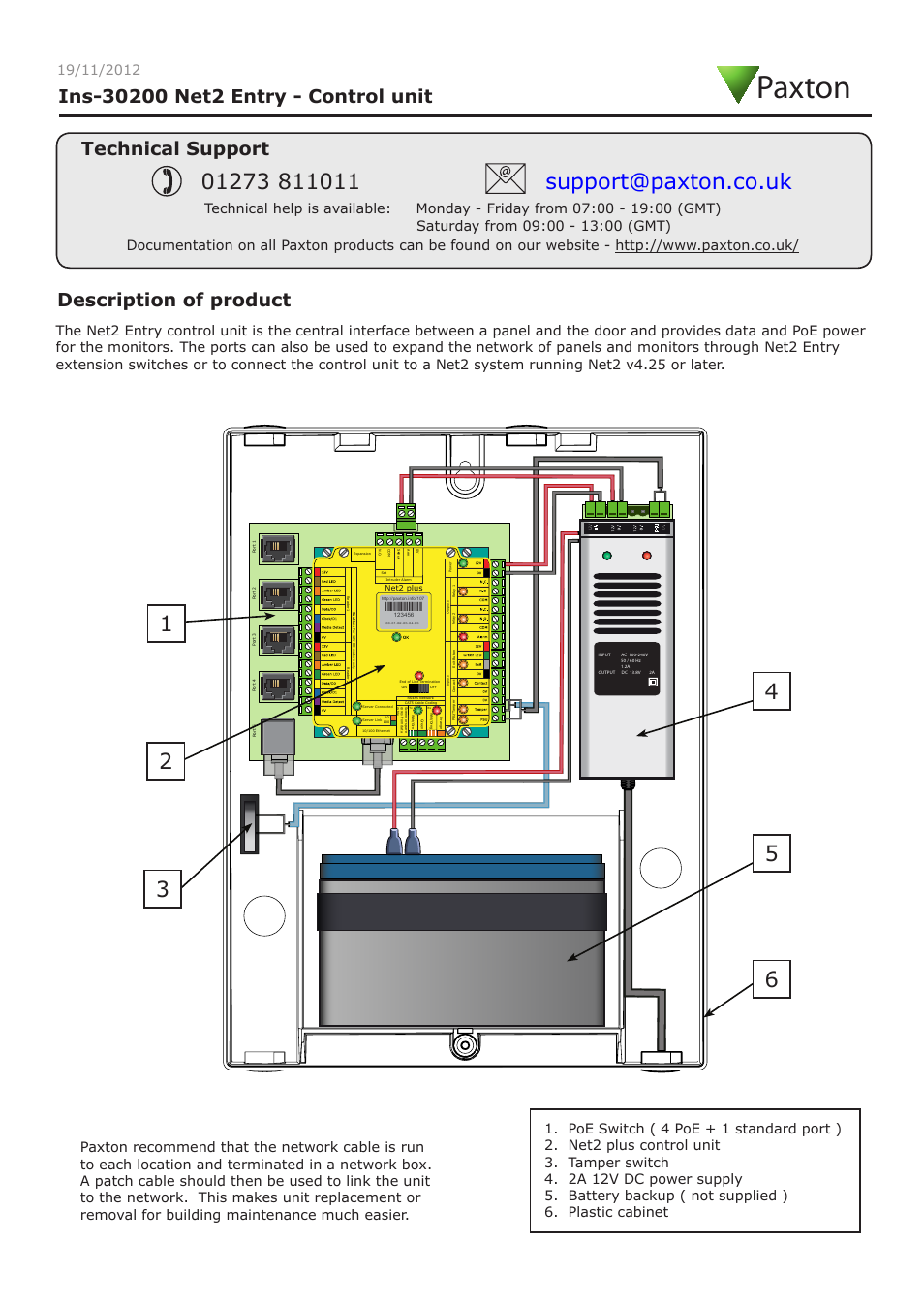
Paxton net2 wiring diagram. Paxton net 2, breakglass/call point wiring with maglock door lock and power supply. With reference to the diagrams, determine where. Installation for the paxton access net2 plus system
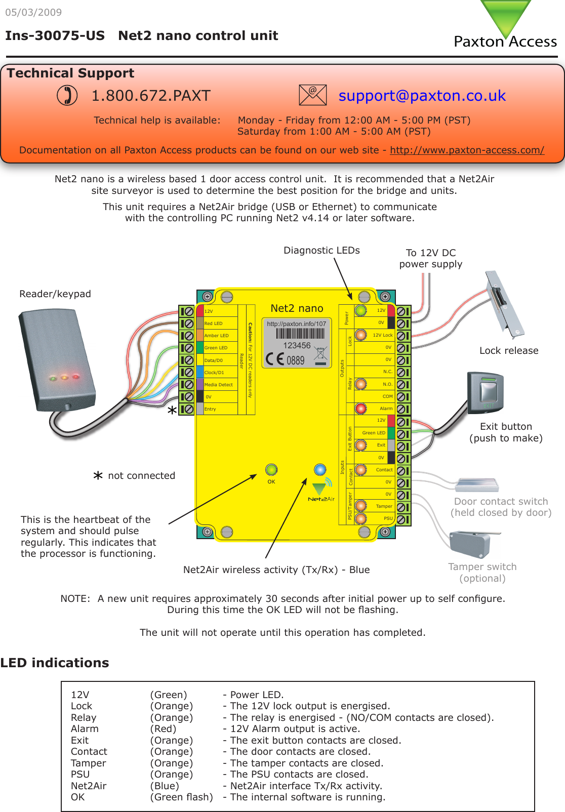
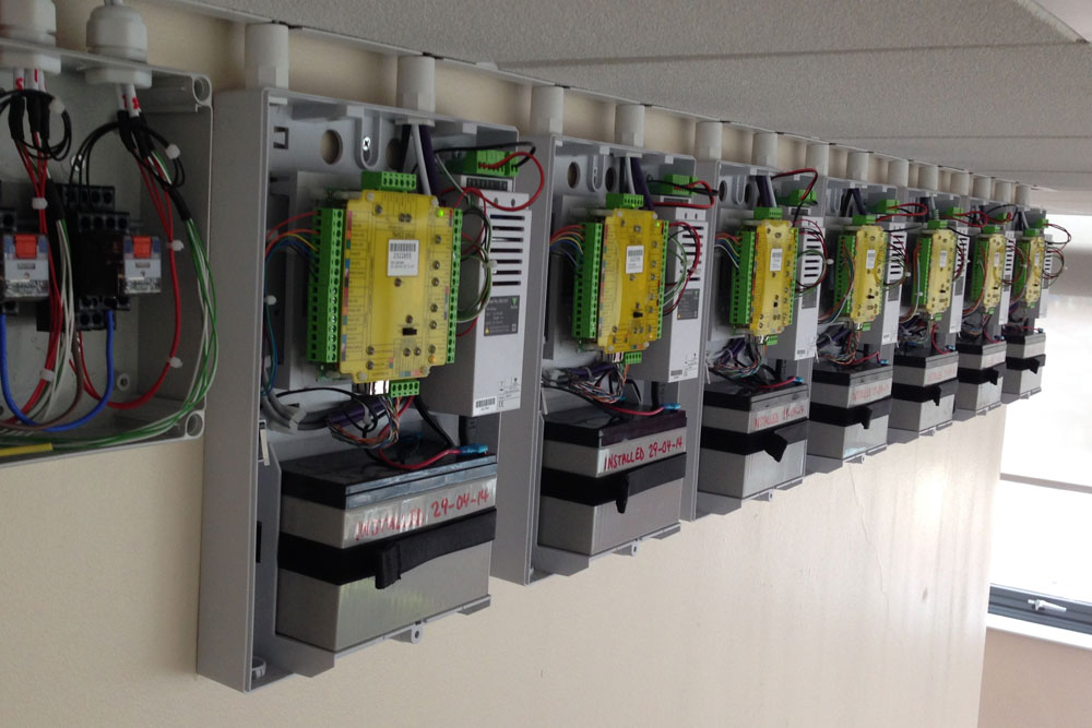
Power supply, with an output in the event of mains failure. A charging circuit for the addition of battery back up and an enclosure tamper switch. This unit contains a net2 acu, a 2a 12v d.c.
This distance can be increased by using paxton high speed Schematron.org 1 r ed ae. Not all of the equipment shown needs to be installed on.
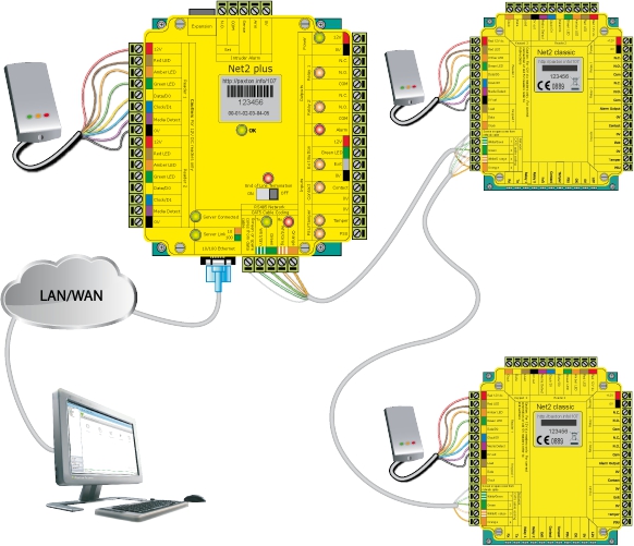
From the net2 entry controller. An rs485 data line has a km maximum length. The biolite n2 needs to be configured via suprema's software.
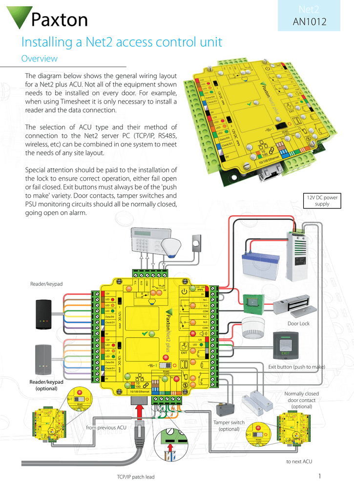
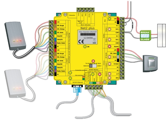
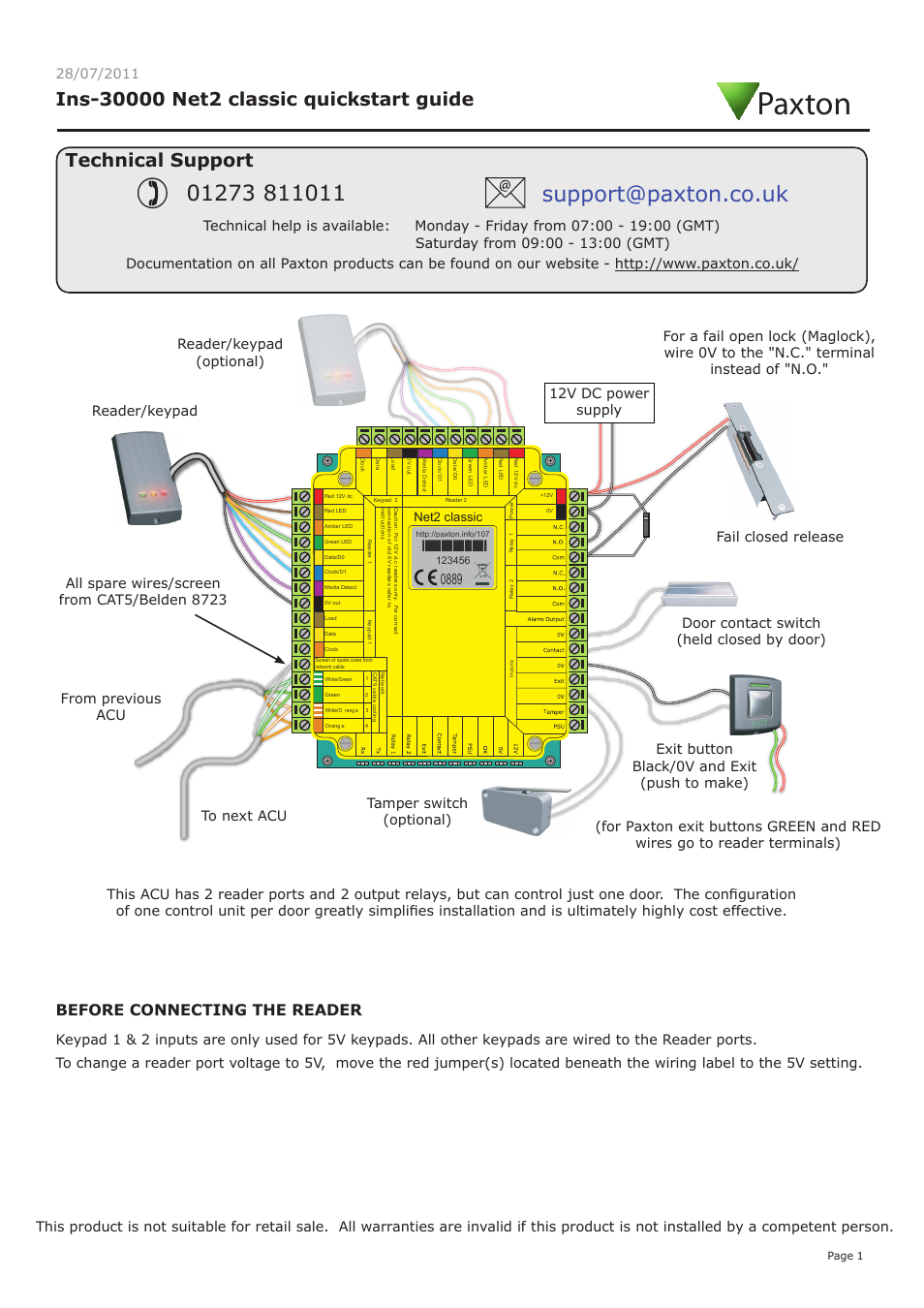
31.08.2018 31.08.2018 3 comments on paxton net 2 wiring diagram the diagram shows a net2 system communicating over a. Paxton net2 plus reader/keypad (optional) reader/keypad from previous acu to next acu tamper switch (optional) exit button (push to make) normally closed door contact (optional) door lock 12v dc power supply an1012 net2 the diagram below shows the general wiring layout for a net2 plus acu. The biolite n2 needs to be connected via wiegand to the acu via the wiring diagram.
Most manuals provided are in the pdf file format. Of ip, battery powered, door entry and wireless or wired door controllers to suit any site **paxton connect admin app only works with net2 pro v or above. Net2 v4 2 installation of a net2 classic in a psu enclosure the best way to install a classic acu is in the specially designed paxton power supply enclosure.
Mount the panel in its backbox. When the operator presses the apply button these changes are stored in the database. Inputs on the net2 acu to accept an alarm signal from a fire alarm system to automatically open specified doors during an alarm condition.
The diagram below shows the general wiring layout for a net2 plus acu. Net2 server net2 program pc the diagram shows the basic structure of the net2 software. • no need for specialist wiring diagrams.
Connecting a suprema biolite n2 reader to net2 overview 3rd party the biolite n2 is an ip based fingerprint reader, it includes a wiegand output for easy connection to the net2 access control system. \program files\paxton access\access control\net2.exe the. Net2 plus is paxton's most powerful door controller, which uses tcp/ip technology to allow direct connection to the ip network, saving time with minimal wiring needed.
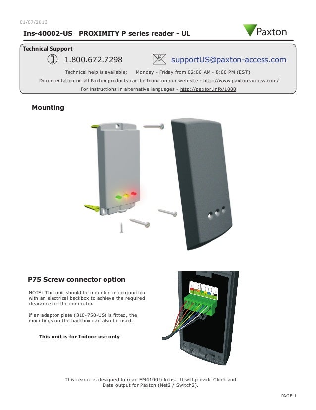
This greatly increases the number of installation options available to the installer. The net2 server will detect that a change has been made to the database Determine the height for the camera and then mark and drill the cable hole with reference to the fixing diagram.
Resistors switched or wired across both data pairs at each end. Any of the four inputs on a net2 acu, (contact, exit, tamper or psu), can be used as a fire alarm trigger. Not all of the equipment shown.
Recently, we undertook our first review of an access control solution, paxton's net2 plus, which is distributed locally by. Of ip, battery powered, door entry and wireless or wired door controllers to suit any site **paxton connect admin app only works with net2 pro v or above. Adobe reader® or equivalent pdf viewing software are required to read these manuals.
Net2 plus is paxton's most powerful door controller, which uses tcp/ip technology to allow direct connection to the ip network, saving time with minimal wiring needed. Connect the net2 entry panel to controller. Net2 v3 supports the use of multiple comports, allowing for star configuration networks from the pc.
Clear colour coding of reader cables leads to fewer mistakes. The diagram below shows the general wiring layout for a net2 plus acu. Control units are automatically detected.
An operator changes a user's validity using the net2 program. Instruction manual for the paxton net2 i/o board. Net2 professional can be configured to use one of the.
Power up the panel from controller. De net2 gebruikers interface is een gebruiksvriendelijk programma dat door de operator gebruikt kan worden om veranderingen aan te brengen en systeem details te bekijken. The maximum between reader and controller is 50 metres.
C:\program files\paxton ac cess\access control\net2.exe de database de hoofddatabase heet net2systeem.mdb.
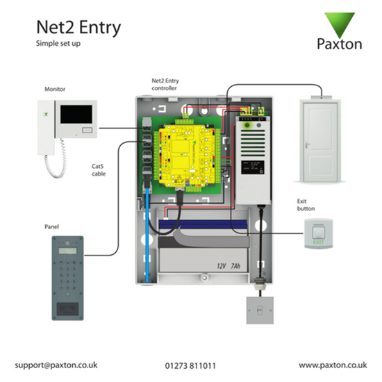
Paxton Access. Net2 Entry A basic system
Paxton Net 2 Wiring Diagram
Paxton Net 2 Wiring Diagram

Paxton Net2 Entry Wiring Diagram Wiring Diagram

Paxton Net 2 Wiring Diagram
Paxton Door Access Wiring Diagram

Paxton www.just.at
Paxton Net 2 Wiring Diagram
Paxton Net2 Plus Wiring Diagram Wiring Diagram
Paxton Net 2 Wiring Diagram
Paxton net2 plus installation manual
Paxton Net 2 Wiring Diagram
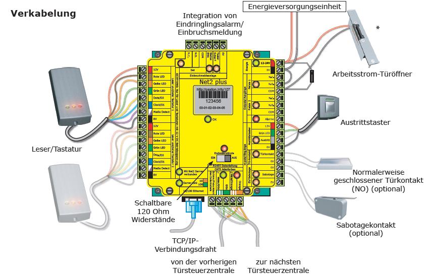
Net2 PLUS Türsteuerzentrale leistungsstarke Steuereinheit für Zutrittskontrollsystem Net2
Paxton Net2 classic quickstart guide User Manual 4 pages
Paxton Access. Net2 plus wiring training card

Paxton Door Access Wiring Diagram


Paxton Net 2 Wiring Diagram
![]()
Paxton Net2 Plus Wiring Diagram Wiring Diagram
Paxton www.just.at